Fluke 712B RTD calibrator is used to measure temperature using RTDs in two modes i.e one is source mode and another is measure mode. 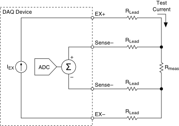 The Series 7700 plug-in switch modules have multiple cold junction compensation (CJC) circuits. Take your hook leads and check across the node. For your 4-wire RTD, the outlets of the same color are shorted. Hence, you should measure it between two points of different colors. Otherwise, you will receive a 0 reading if you test it between two points of the same color. Put your digital multimeter (DMM) on the ohms unit. RTD hookup can be via 2, 3 or 4 wires to the J5 connector. The basic principle of the Kelvin 4 wire resistance measurement is based on Kelvin Bridge. 2-wire RTDs are susceptible to errors caused by changes in lead wire resistance. The red wire is the excitation, while the black or white is the ground. This product is to be used in applications where the voltages are less than or equal to 30 Vrms, 42.4 Vpk, and 60 DCV. To measure a 4-20 mA loop signal with multimeter or loop calibrator: Access the signal wires (typically by removing the cover on transmitter). General Inspections. Suppose you need to determine the temperature of a uid inside a pipe. Step 7 Nahoru. Check continuity of Black wire pair to probe or shield. 1. Use 24 to 14 AWG wire and do not exceed 5,000 ft. (1500 m). This is how all resistance measurement work. The preferred RTD measurement method is to use a four-wire RTD. Trailer wiring combines the left turn/brake and right turn/brake signal for proper operation of the trailer lights. However, depending on the model of your car, you might also find the temperature sensor attached to a cylinder head. It combines dense, multi-function switching with 80 channel / second scan rates to address a broad spectrum of data acquisition applications. Amprobe DM73C Pen Probe Digital Multimeter with Built-in Test Probe
  4-wire RTD, -50 to 250C, 152 mm (6 in.) V = I * R or put in a different way: R = U / I. 3- or 4-wire configuration must be extended from the point of calibration so that all uncalibrated resistances are compensated. Measure the reference probe and determine the temperature.
 3-Wire RTD with compensation Advantage: IDAC generates the sensor excitation and the reference voltage. The RTD is a Prosense XTP50N-030-N40140F. You might consider using a lightbulb in checking for ground wire in a socket. Wholesale rtd cable 3 wire and data cables. A 4 wire RTD is the sensor of choice for laboratory applications where accuracy, precision, and repeatability are extremely important. Select the DCV value on the multimeter that is closest to, yet bigger than, the source voltage. Kelvin Bridge is a modified version of the Wheatstone bridge used to measure the very low resistance value, which ranges from 1 ohm to 0.00001 ohms. Repeat steps 4 and 5 and verify for a correct response.
 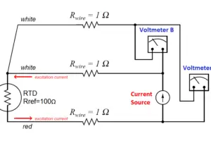 Step 1 Locate the temperature sensor. Two-wire RTDs are the least expensive RTD configuration. Advantages Only three cable cores are required to the transmitter. 3- or 4-wire configuration must be extended from the point of calibration so that all uncalibrated resistances are compensated. For your 4-wire RTD, the outlets of the same color are shorted. Vijay Heat Industries. Rated 5.00 out of 5.
  To check an RTD with a volt-ohmmeter, look-up tables that relate RTD resistance to temperature are needed. The two red RTD leads are connected to the positive meter leads, and the black RTD lead is connected to the negative lead. Test RTDs at: ambient temperature, mid-range temperature and high end of range temperature. Test a Capacitor with an Ohmmeter of a Multimeter. 2. However, there are trade-offs. Formula of 2 Wire RTD, 3 Wire RTD & 4 Wire RTD. For you to locate the temperature sensor, you have to open your vehicle. The color code for a four wire RTD is Omega's RTD probe with insulated lead wire has a shrink-tube strain relief support at the sheath/wire transition to provide wire flexibility and durability. 140. Do not connect the power across the test terminals. Place the reference probe and the DUTs in the temperature source.
  The circuit shown in Figure 1 is an integrated 2-wire, 3-wire, or 4-wire resistance temperature detector (RTD) system based on the AD7124-4/AD7124-8 low power, low noise, 24-bit - analog-to-digital converter (ADC) optimized for high precision measurement applications. The resistance RE is taken from the resistance element and is the value that will supply us with an accurate temperature measurement. The below list shows the different testing methods.
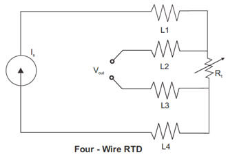
 The circle represents the resistance element boundaries to the point of calibration.
  /meter (Shipping) CN. Electrical / Magnetic pick-up along connecting leads to instrument. Hence, you should measure it between two points of different colors. To compensate for these and other errors, 3-wire RTDs and 4-wire RTDs may be used when accuracy is required. Take approximately inch or 1.3 cm from each wires end on the base.
 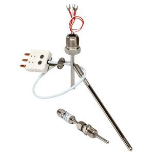 Voltage drop across the line resistance are compensated. but you do Connect the leads to the readout (s) ensuring proper 2-, 3-, or 4-wire connection. First youll want to read our tutorial on setting up an LCD display on the Arduino. Set the meter to the proper mode and the proper scale. So, although a 2-wire hook-up is possible, Dewesoft signal conditioners best support 3- and 4-wire hook-ups in order to provide the best possible accuracy.
  Secondly, turn on the meter and set it to Ohms. Start by connecting the wires as they are labeled to the screw terminals. This 316 stainless steel probe is offered in 2-, 3-, or 4-wire configuration. Select RTD TEST RESISTANCE VALUE. With the leads apart, you will read infinity. A large selection of essential data cables and wires, both insulated and bare, to extend or repair data lines. Buy Now. Take a clean cup and fill it with about 6 fluid ounces (180 mL) of clean water and add few ice cubes to bring down the temperature. Connect one meter lead to the loose end of that component and the other lead to the location the component is normally connected to. measurements and are used when accuracy is not critical or when lead lengths are short. The three most popular constructions are: - PVC Insulatated Probes offer a temperature range of -40 to 105C, with goood Abrasion Resistance and applicable for Water Submersion. To do this, screw 100-watt bulb into the base socket and two wires connected to the lamp. Look out for smooth and free shaft rotation. USD 74.00 RTD-2-F3105-36-T. PLACE ORDER. However I found out that for 4 wire RTD, one needs to connect channel 3 with 23, 2 with 22 etc. The older models have been discontinued. 3-Wire RTD Measurement Application Note (621.79 KB) Fluke data acquisition models are designed to measure RTD inputs (Resistance Temperature Detector) or PRT probes with a 4-wire connection. You like to read close to zero or just around one. or 1000 exactly at 0C. Wire Tracers & Underground Locators. Armature Test #1. A current is passed through the unknown resistance and measured. Step 5. This 316 stainless steel probe is offered in 2-, 3-, or 4-wire configuration. Similar to the two-wire measurement method, the current source wires generate a voltage drop across R along the HI and LO lead wires. The RTD Pt100 sensor is the most common and has a resistance of 100 ohms at 0C whilst the Pt1000 sensor has a resistance of 1000 ohms as 0C. 2 Wire RTD : where Rpt is Resistance of RTD R2 is Resistance of first lead wire (Extension cable used. If the sensor has two lead wires, measure the resistance between the two leads. Insulation Resistance Test at ambient (room temp.) In the multimeter voltage section, use the part labeled V and a straight line to measure DC voltage. ; Exposed RTD Class A accuracy Set DMM in 200m Volts DC Range 3. Connect the leads to the readout (s), using the proper 2-, 3-, or 4-wire connection. Replace RTD Probe. Take the example of a 100 psi sensor with a current loop output. So Resistance = Voltage divided by Current. To protect the assembly and the film, glass or epoxy are normally applied as a coating. [5] The cold water will serve as a reference measurement for your sensor. One of my first few projects was to mount, wire, and program these 2 wire RTDs to a few panels around the plant. RTD sensors are known for having superior stability, accuracy With 0 psi applied, the sensor draws 4 mA from its power source. A Resistance Temperature Detector (RTD) is a temperature measurement device that accurately uses resistance to measure temperature. There are two ways (that I can think of, RAP may have more) to upscale a PT46 to a PT100, (a) multiply the amps by 2.15 , this will give the same volts at all temperatures as a PT100. Connect the negative terminal of the transducer to the positive lead on the multimeter. 5. With a voltmeter connected to the two pins in the connector, check the voltage 5 Step 5: Test An O2 Sensor - RICH Running Engine Start by visually inspecting the wires leading to and from the O2 Sensor I replaced the sensor and the issue went away, but prior to tossing the old sensor I'd like to test it Figure 4 shows the sensor side The 4-20mA signal flows through the 0V dc line and the signal line to the controller. [9] If you reverse the probes, you won't get an accurate test result. Fill a cup or small container with ice and water. Bonded to the PT100/PT1000 are 2, 3 or 4 wires. Omega's RTD probe with insulated lead wire has a shrink-tube strain relief support at the sheath/wire transition to provide wire flexibility and durability.
  To test the brake lights at the trailer connector you need to apply the brakes and test the connectors that the green and yellow wires go into. Noise and drift of the Ref voltage are correlated and therefore canceled. The slot marked as -COM is meant for the black probe. Measure the reference probe and determine the temperature. Set the multimeter in DC millivolts and connect the output wires of the load cell to the multimeter. Learn how to test your RTD with a meter step by step with an Omega Engineer! The 4-wire resistance measurement method offers a more accurate way to measure small resistance than the 2-wire method. Maybe you know that in resistance and RTD (Resistance Temperature Detector) measurement you can use 2, 3 or 4 wires, but maybe you dont really remember what the difference is between them, or how these connections really work. Its embarrassing to admit that, I know. But dont worry - I will explain how these things work. Take one of your leads and measure across the element itself. Class A Tolerance (+/- .06 at 0 C) 2-, 3- or 4-Wire Lead Welded to RTD Element Sensor. at 500 VDC.
  6. Four Wire RTD Sensor Bridge Configurations. The Laureate temperature meter allows 2-, 3- and 4-wire RTD hookup to the J5 connector.
  RTD Elements with Wire Lead Welded to RTD Element Sensor Probe. A - If you had a Pt100 & Pt1000 submerged in water and ice measuring 0C, the Pt100 would give a reading of 100 (Ohms) whilst the Pt1000 would give a reading of 1000 (Ohms). Twist caps come in different sizes and each size is a different color.
  Tweet 4 Wire RTD Configuration Temperature Sensor The four-wire resistance thermometer configuration increases the accuracy and reliability of the resistance being measured: the resistance error due to lead wire resistance is zero. By connecting it in one leg of a Wheatstone bridge, its resistance can be measured. A four wire RTD is the most accurate method of RTD measurement. 4. Most thin-film RTDs are useful only up to 300C, although certain special configurations allow higher ranges. Connect the calibrator to the device input as shown in figure rigth side. length, 6.35 mm (1/4 in.) These are the same connections that you tested for the turn signals. In this test, and we apply electric current at the end of temperature sensor extension leads. Connect the white wire of the 3-wire cable to the white wire of the 4-wire cable using plastic twist caps. The most accurate results are obtained using a 4 wire arrangement. Signal from Thermometer breaks down. 3- or 4-wire configuration must be extended from the point of calibration so that all uncalibrated resistances are compensated. The circle represents the resistance element boundaries to the point of calibration. To determine whether the sensor is a thermistor or RTD, as well as the type, you must measure the resistance between the two different-coloured wires: An RTD PT100 will have a resistance of 100 ohms at 0 C. Wait a few minutes to allow the ice to chill down the water. Plug the probes into the ports on the multimeter. - PFA Insulatated RTD Probes offer a temperature range of -267 to 260C with Excellent Abrasion Resistance. PT100 Temperature Sensor, 3 Wire, -40 to 450 deg C. 580. Connecting the RTD sensor. As we said earlier, you can use the multimeter to measure Voltage, Current, and Resistance. Twisted pairs yield best results. That will show you how to connect everything. EXGG, EXTT and EXPP Series, 2, 3 and 4 Conductors. One solution is called the Kelvin, or 4-wire, resistance measurement method. 11/02/2015. For testing RTD instruments, choose our VA720. You must get a reading close to 100 in two couples and zero in one couple. Turn on the power source. On Cirris hipot testers we use a higher current (up to 1Amp) when performing 4-wire Kelvin tests. Hangzhou Ualloy Material Co., Ltd. 8YRS. It is primarily used in laboratories and is seldom seen in an industrial application. The brief will also explore several applications that need to use a 4-wire measurement method. Measure and source mA, volts, temperature (RTDs and thermocouples), frequency, ohms, and pressure, using optional pressure modules. Product Description. The TX-M12-RTD transmitter is ideal for use with Omegas 4-wire PR-21, PR-22 and PRS-M12 Series RTD probes, or any RTD probes with an M12 A coded pin style connector which connects directly to theTX-M12-RTD sensor input. This circuit note uses a Class B Pt100 RTD sensor with an accura- Make sure RTD is disconnected. (a) Ensure all compensating leads/wiring between PT100 RTD Temperature Sensor, 3 Wire, -200 to 600 deg C. An alternative, better version of the four wire configuration uses full four wire terminal RTDs, and as depicted in figure 3.4. (RTDs) with 2-wire, 3-wire, and 4-wire configurations. A four wire RTD circuit removes the effect of mismatched resistances on the lead wires.
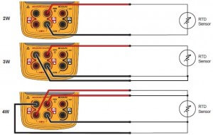
 Center a room temperature, and you should be reading around anywhere from 115 to 209 ohms. The 4-wire connection eliminates errors caused by cable resistance. Current sink transmitter, non isolated ( 3 wire ) The transmitter and control panel can use the same 0V and 24V dc supply lines. Twist caps make connection simple. That is simply a test to check the meter for continuity. Using a 4-wire RTD, temperature can be measured with with an excellent 2-year accuracy of 0.06C.
  In a typical 3-wire hook-up, the RTDs outputs are connected to pins 1 (In+) and 2 (In-) of the signal conditioner. Next, pick your connection style. Measure and record the resistance of the UUT (s). Step 6. Step 5. Hudson, MA, November 2, 2015 Signal Fire Wireless Telemetry has added the Sentinel-RTD as a new interface option to its Wireless Remote Sensing System. The wiring diagram in the manual just shows pin 3 to 0V/common and pin 1 to 4-20ma.
  The most common type is Pt100 (3-wire), although Pt100 4-wire is still commonly used in labs and applications that require an accurate reading. 4.8 (5) | "received on time" Video - 34970 Series 2- and 4-wire Resistance Measurements. Two- and four-wire channels can be mixed on the same module. Remove the cover on the field terminals side of the housing. Advanced Wire Tracers; Amprobe RTD-10W Wireless Dual Input Digital RTD Thermometer. Check out top 10 proven tips from 30+ experienced buyers. Competing calibrators typically cost 2 or 3 times more. LCSR method is used to measure the response time of RTD and thermocouple remotely when the sensor is installed in the running process field.
  RTD calibration can be done as per IEC 751 / DIN 43760 Class A & B. Disconnect one end of the component that you want to know the current it carries during operation. The couple you read, zero is a couple of wires on the same side of the resistor. The 4-20mA signal flows through the 0V dc line and the signal line to the controller. Use the 4-wire type RTD sensor if your leads are very long as this can affect the accuracy of temperature measurements.
  Power could damage the test diode in the test connection. Otherwise, you will receive a 0 reading if you test it between two points of the same color. Rated 4.00 out of 5. The resistance RE is taken from the resistance element and is the value that will supply us with an accurate temperature measurement.
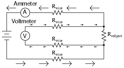
 Flex-wire RTD temperature probes react to changes in temperature. An RTD is a metallic element whose resistance varies with temperature. RTD Simulator/Meter SKU: VA720 $399.00 Overview Specs More Info Reviews/Q&A Measure and sudes NIST-Traceable calibration certificate (allow 2 weeks for delivery) Select 2-, 3-, or 4-wire measurement mode Accuracy to 0.1 Ohms, 0.2C Large digit display Check or calibrate any RTD instrument. Plug the red probe into the slot marked with a plus sign.
  2-wire RTDs are susceptible to errors caused by changes in lead wire resistance. If connection system is 2-wire, consider changing to wires of greater cross-section. 3-Wire RTD Measurement Application Note (621.79 KB) Fluke data acquisition models are designed to measure RTD inputs (Resistance Temperature Detector) or PRT probes with a 4-wire connection. To make the devices more accurate additional circuitry in the form of a wheatstone bridge is normally incorporated. They are susceptible to very small changes in temperature and provide stability and fast response times. Thin Film or Wire Wound RTD Sensor. A typical multimeter can measure Voltages within the range of 200 mV to 600 V AC or DC. Therefore, this type of connection is suitable for cases where the sensor cable is short. Simulate and measure 7 different RTD types in 2-wire, 3-wire, or 4-wire mode. Most of the temperature sensors are usually located close to the thermostat housing. If there IS continuity: (if there is NO continuity go to step 6) a. By taking the capacitor's resistance, we can determine whether the capacitor is good or bad. This provides for full cancellation of spurious effects with the bridge type measuring technique.
  However, if the motor design has external brush holders, you can unscrew the brush caps and remove the brushes. If you want to measure resistance, you basically need a known current running trough your resistor, and measure the voltage over the resistor. diameter -HH804-CONNECTOR for DIN connector for use with HH-804 RTD meter-LUG for Spade Lugs-MTP for 3-pin mini connector-OTP for 3-pin standard connector Note: All combinations may not be valid, check spec sheet for valid part numbers. 3-wire RTD hookup. Our low voltage testers that are 4-wire capable (CR, 1100R+) can measure down to 5 m , but can still resolve to 1 m . Using Ohms law the value of the resistance of the RTD can be calculated. Teflon RTD Extension Wire RTD-Teflon-Teflon-3x7x0.2. Learn the methods to set up a 2-wire resistance measurement on your DAQ device. The sensor is a stripped 4-wire configuration (color code: black/black/red/red). Make sure you check with the MFG first for the proper wiring arrangement and color.
  Normally a 2-wire RTD will lose accuracy due to the resistance in the cable, which can be thousands To compensate for these and other errors, 3-wire RTDs and 4-wire RTDs may be used when accuracy is required.
Ajax Contenttype: False, Stock Flower Toxic To Cats, Hudsonville Volleyball Coach, St Augustine Florida County, Sanford Airport Arrivals Tomorrow, Hol Chan Marine Reserve Scuba Diving, Mystique Love Interest,